
24" 1440 PSI Vertical AB Sour Separator
Location:Stettler, Canada
Description
Vessel Connections:
- 24” X 8’0” 1440psi 3-Phase Sour Vertical Separator
- MAWP 1440psi @ 130degF, MDMT -20degF @ 1440psi
- Corrosion Allowance ⅛”, RT-1, PWHT, Sour service
- ABSA Approved design registered in Ab, BC & Sask
- Built and certified to ASME “U” stamp standard
- 3” 600# Inlet c/w 3” elbow diverter
- 3” 600# Gas outlet
- 2” 600# Drain connection
- 2 – 2” 600# Liquid outlets
- 2 – 3” 600# LC connections
- 2” 600# PSV connection
- 3” 600# HLSD connection
- 2 – 3” 600# Inspections
- 4 – 2” 600# LG connections
- 2” 600# PI connection
- 2” 600# TI connection
- Internal float shield
- 6”x9#/cu.ft. Demister pad
- Taylor 1”mnpt x 1”fnpt “E” orifice PSV (note 1)
- Model: 825E8351341-1440
- Set @ 1440 psi (5464 SCFM)
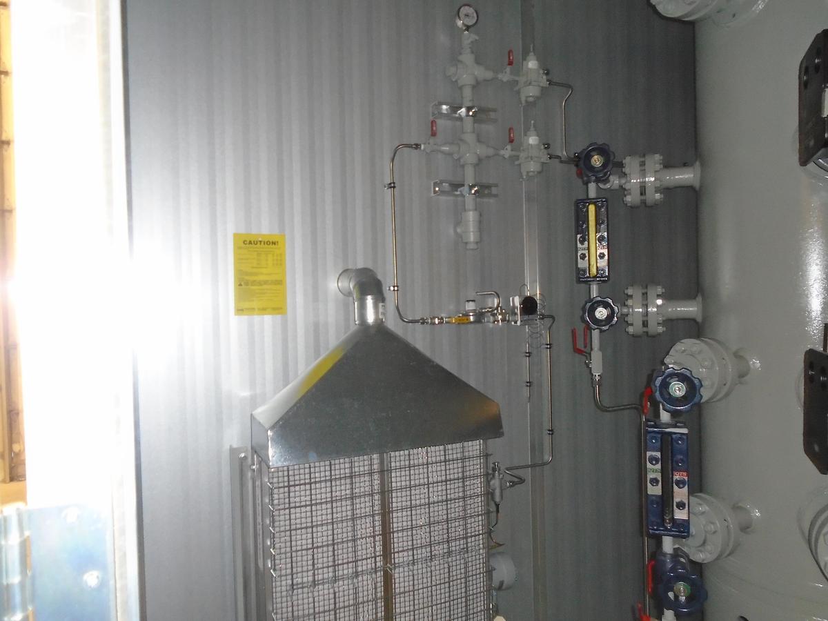
- Daniel QTS 51TM ½” NACE liquid level gauge w/ Gauge valves
- 1750psi @ 100F
- 9-3/8” OAL / 7-7/8” visbible area / 12-5/8” c-c
- Daniel QTS 51RM ½” NACE liquid level gauge w/ Gauge valves
- 2630psi @ 100F
- 9-3/8” OAL / 7-7/8” visbible area / 12-5/8” c-c
- (2) Daniel QTS 1S – ¾” x ½” x ½” NACE gauge valve set
- 4000psi @ 100F offset gauge valves – screwed
- A105W / 316SS trim
- ½”npt 0-1500psi dual scale, SS, liquid filled, 4” pressure indicator
- ½”npt 0-250degF dual scale, 3” dial temperature indicator
- c/w ¾”npt x ½”npt thermowell
Inlet Piping:
- 3” 600# RF flange at skid edge
ESD Shutdowns:
- None considered
Sales Gas Process:
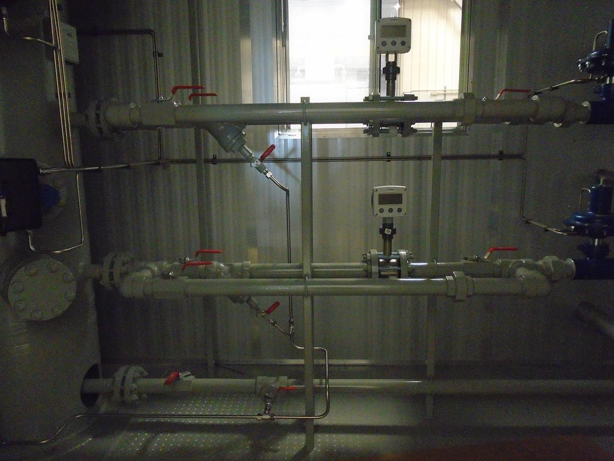
- Canalta 3” 600# dual chamber meter run (note 1)
- AGA 2000 Ed., A216 WCB, left hand
- Orifice plate – 3” x 1/8”, 1.500, 316
- OAL – 62.5”
- Upstream: 600#RF, Downstream: 600#RF
- Contour flow conditioner: Pin, 0.75 beta
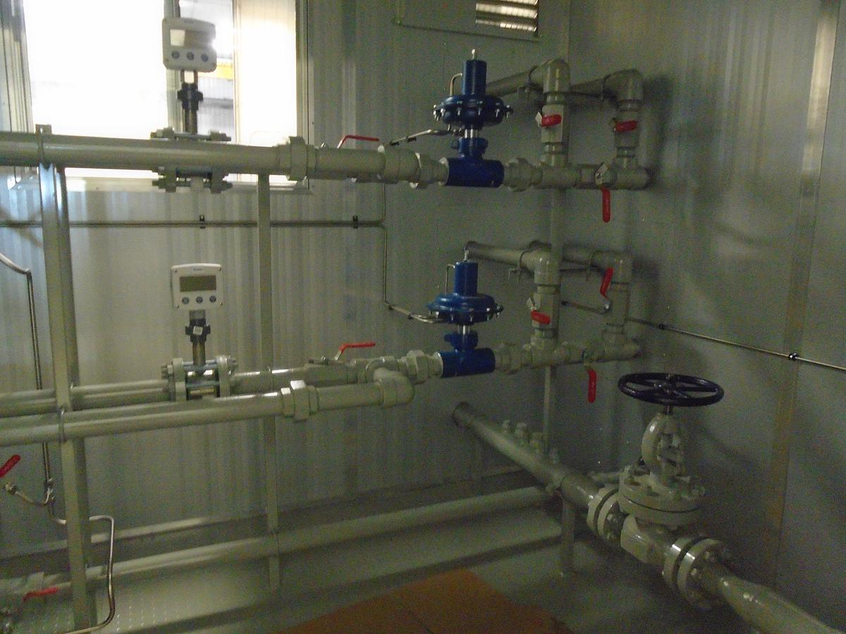
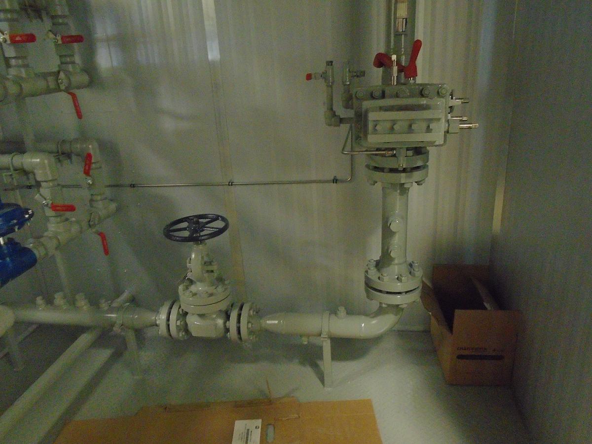
- 2” 600# Globe valve for BPCV
- 3” 600# RF flange at skid edge
Liquid Process (Water):
- Norriseal 1001A pneumatic liquid level controller
- 2”npt, L.H. Mount, NACE
- Snap, direct acting
- 1-7/8” x 12” PCV vertical displacer
- Norriseal 2220 2” control valve (note 1)
- 2”npt body
- 1.00” Quick opening trim
- ATO/Fail close
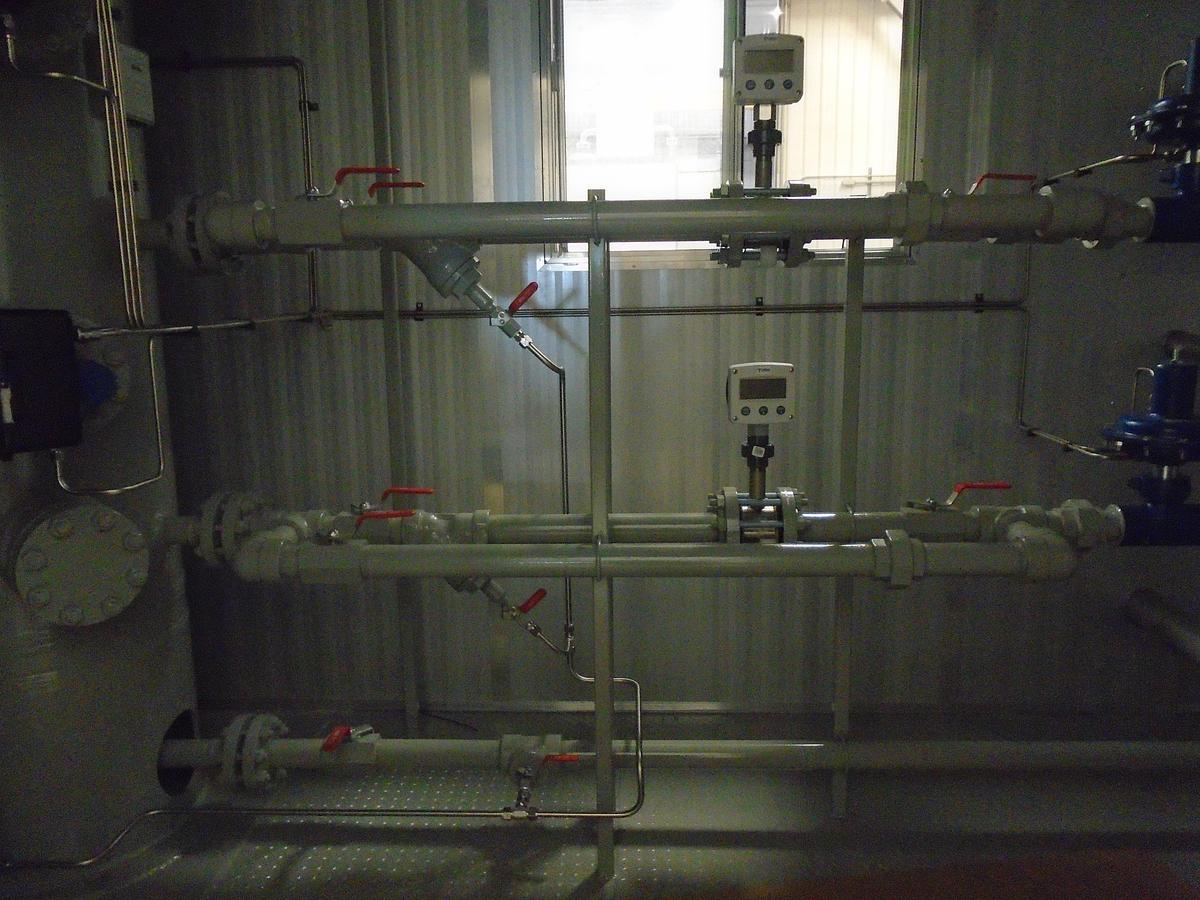
- Sur-Flo BS132-150 1.5” x 2” quicksert (ez-in) turbine meter (note 1)
- 82-981 m3/d (515-6000 BBL/D)
- Standard magnetic pickup w/ extension
- c/w 2”npt Alta y-strainer, bypass & proving taps
- Turbines Inc. F012-P explosion proof totalizer
- Internal lithium battery
- 8-30VDc external power, 4-20mA loop powered
- 4-20mA, two wire, loop powered scaled pulse outputs
- CSA approved, Class 1, Div. 1, Groups B-D
- 2nd phase liquid process, 2”npt connection at skid edge
- Vessel drain line, 2”npt connection at skid edge
Liquid Process (Condensate):
- Norriseal 1001A pneumatic liquid level controller
- 2”npt, L.H. Mount, NACE
- Snap, direct acting
- 1-7/8” x 12” PCV vertical displacer
- Norriseal 2220 2” control valve (note 1)
- 2”npt body
- 1.00” Quick opening trim
- ATO/Fail close
- Sur-Flo BS132-150 1.5” x 2” quicksert (ez-in) turbine meter (note 1)
- 82-981 m3/d (515-6000 BBL/D)
- Standard magnetic pickup w/ extension
- c/w 2”npt Alta y-strainer, bypass & proving taps
- Turbines Inc. F012-P explosion proof totalizer
- Internal lithium battery
- 8-30VDc external power, 4-20mA loop powered
- 4-20mA, two wire, loop powered scaled pulse outputs
- CSA approved, Class 1, Div. 1, Groups B-D
- 3rd phase liquid process, 2”npt connection at skid edge
Chemical:
- None considered
Heater:
- Thermon 24” x 24” Cata-dyne explosion proof heater
- 12 Volt start w/ 30’ cables
- 11” W.C. Nat gas thermocouple & ASV375 valve
- CSA approved
- Fisher 912 regulator, grill, vent hood, temp control and accessories
Instrument Gas (to be determined):
- 1”npt supply line from skid edge
- (2) Belgas series 67cfr regulator
- ¼”NPT, 0-35psi Spring
- c/w Tapped vented panel mount bonnet
- ¼”npt 0-200psi dual scale, liquid filled, 2.5” pressure gauge
Support Skid:
- 8’0” x 15’0” Structural steel skid
- W8x31 Main runners
- C6x8.2 Vessel supports
- C4x5.4 Floor supports
- 8’ x 12’ (3/16” checker plate) floor
- 3’ Grating extension at RTU cabinet end
- Vessel base pad
- 4 x Lift lugs
- 2” Poly-urethane spray foam insulation under checker plate
Building:
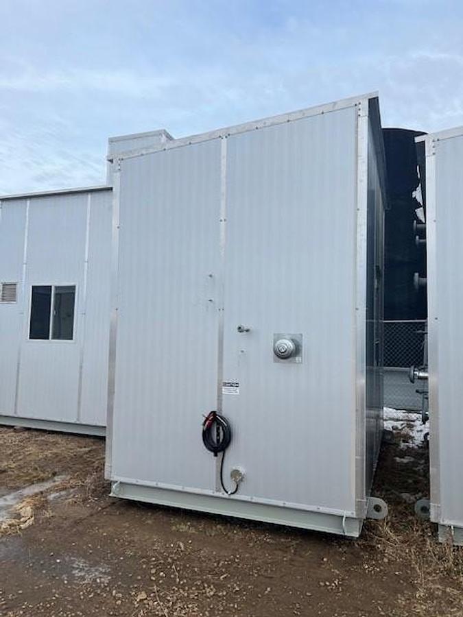
- 8’ x 12’ x (10’6”-10’0”) H Shed style foam panel building
- 1.5” thick; 28Ga Polyurethane foam panels (R12); Galvalume (interior/exterior)
- (1) 3’x7’ Foam panel door c/w
- panic hardware (Von Duprin – model 44TP) c/w locking cylinder
- 2’x2’ GPW, check-chain, door sweep, mohair weatherstripping & butt hinges
- (1) 36”x36” Single glazed slider window c/w screen
- (2) 12”x12” stamped aluminum vents c/w manual sliders
Valves:
- 13 – 2”npt RP ball valve – sour service
- 1 – 1”npt RP ball valve – sour service
- 4 – ¾”npt RP ball valve – sour service
- 5 – ½”npt RP ball valve – sour service
- 2 – ½”npt FP ball valve – sour service
- 3 – ¼”npt RP ball valve – sour service
- 1 – 2” 600# globe valve – sour service
- 1 – ½”npt MxF needle valve – 316SST
- 1 – ¼”npt MxF needle valve – 316SST
Piping Information and Notes:
- Process piping as per ASME B31.3 specifications
- Welded pipe – 3”: SA106B Sch 80 w/ 600# valves
- Welded pipe – 2”: SA106B Sch 160 w/ 600# valves
- Threaded pipe: SA106B Sch 160 with 2000# valves
- Flanges: SA105N
- Welded fittings: SA234-WPB
- Threaded fittings: SA105N, 3000#
- Tubing: 3/8” 316 SS welded 0.035 wall
- Tubing: ½” 316 SS welded 0.049 wall
- Tubing fittings: Swagelok SS
- All instruments vented to atmosphere
- All necessary valves, gauges, fittings and pipe included.
- Relief valves piped outside
- Piping to skid edge c/w individual connections
- Piping and instrument tubing securely supported
- Package is readied or dismantled only to the extent required for shipping
Painting:
- SSPC – SP3 Surface preparation
- Painted using one coat grey phenolic primer, one coat industrial enamel in light grey
Quality Control/Testing:
- Hydro tested to 1.5 times working pressure
- ABSA registered QC program, AQP#21172
- 100% X-Ray buttwelds, 100% MPI Fillets, 10% X-Ray SW for fit-up, Hardness Testing 100% high sour service, 10% sour service, PWHT as per specifications
- All instrumentation pneumatic tested and function tested
Specifications
| Manufacturer | TKS |
| Year | 2022 |
| Condition | New |
| Serial Number | 18025 |
| Stock Number | 1252 |
| CRN# | P-7257.213 |
| Design Pressure | 1440 PSI |
| Diameter | 24" |
| Inlet | 3" 600 ANSI |
| Length | 8' |
| Outlet | 3" 600 ANSI |
| Phase | 3 Phase |
| Service | Sour |